6200 Savoy Drive Suite 750. Slide 18 of 22.
Torque Force Required To Slide A Gate Physics Forums
Sluice gate design.
. - Yahoo Answers Oct 10 2010 we are in the midst of creating a gear system for a water gate project below are sluice gate valves penn-troy manufacturing inc - Sluice Gate Operators. Y2 gate opening or flow depth at sluice gate under non-parallel flow. Bank Under Sluice Gate Type Single gate type steel plate guider structure Scale Clear span 60 ft x gate leaf height 23 ft x 7 gates not including 4 under sluice gates at right bank Replaced Parts Gate leaf and water-tightness structure and sill beams for 7 gates Improved Parts Side flame and roller parts 2.
If the storage level is less than the sluice gate height put in this value X Width of sluice gate in dm G. To calculate the flow through a sluice gate you will need to use a combination of Bernoulli equation and the continuity equation. I want to have your expert advices about a sluice gate design.
Sluice Gate With Flow. 12 ρ v12 ρ g h1 12 ρ v22 ρ g h2 1 where. Discharge under a sluice gate.
Manometers for Half-Meter Flume. V 2 C d 2gy 1. The design mimics the existing 1930s riveted gate construction using modern materials and joining methods.
I have attached a picture of that gate showing loadings and dimensions of gate. Recall that the general Bernoulli equation between two points along a streamline is the following. Sluice gate design guide - ebooks free download - Sluice Gate Design Guide Design sluice gate lifting gear.
Slide 19 of 22. Upstream of the gate and repeat the measurements. Design Calculations For Gate Valves module 4 nptel api600 gate globe valve torque actuator gear operator ansi cl basic calculation of thrust force and torque for gate valve 3 2 design basis valve stem thrust f stem nrc gov maximum allowable stem torque mast piping engineering engineering standard for process design of valves and spindle design for knife gate valve.
At sections 1 and 2 the flow is uniform and the pressure is hydrostatic. They have three main parts. Neglecting bottom friction and atmos-pheric pressure decide the velocities 8 5 and 8 6 and the horizontal force re-quired to hold the gate if D 56 m D 61 m and L5 m.
Slide 15 of 22. The sluice gate flow rate measurement is based on the Bernoulli Equation and can be expressed as. In this paper a height automatic system is designed to set a certain height by using level sensor PLC and a three phase actuator with its transmission gear box.
Jayakarta Sluice Gate is located in Jakarta the capital city of Indonesia. Sluice Gates Used in water diversion canals irrigation canals residual water purification plants drinkable water treatment plants reservoirs and industrial General Comments A sluice gate is a mechanism used to cut off or obstruct the passage of a liquid. Eq 1 p 1 1 2 ρ v 1 2 γ z 1 p 2 1 2 ρ v 2 2 γ z 2 p thermodynamic pressure ρ fluid density.
The combined reduction of the gearbox drive chain and worm gear is 51 x 11 x 251 or 1251. This drive shaft drives a worm gearlifting nut assembly. Slide 17 of 22.
This means it takes 125 revolutions of the motor for one revolution of the worm gear assembly output. All of this equipment was used in two different locations having very different dispositions and types of gold between March 12th and August 5th of 2009. CALCULATE VELOCITY FLOW RATE FROM y1 y2.
Slide 14 of 22. C d C c 1 C c y 2 y 1 12. Kindly guide me about its flexiure and shear design.
The worm gear assembly has a 251 reduction. Weir gates mounted with unseating pressure particularly wide gates are subject to greater leakage because water pressure tends to deflect the slide away from the seals. Sluice gate THREADED VALVES Valves with threaded joints available for the DN15 ½ DN50 2 diameters.
Sluice Gate in Half-Meter Flume. Find all the operator options. Gates up to 20 ft in width are not uncommon.
Such a gate may be only 24 to 30 in. The flood discharging sluicing gate is of reinforced concrete structure the total width is 2400 m the longitudinal length is 1200 it has two 600 m X600 m HxW flood discharge sluicing bottom holes and one 600 m X600 m HxW floating debris sluicing upper outlet. Discharge under a sluice gate.
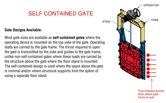
The moveable part of the sluice gate. Each application has a unique set of design variables which will impact the overall design of the gate. Open-channel flow discharge under a sluice gate formulas Victor Miguel Ponce.
Y X 15 Double sluice gate drive 7. We also had a chance to see a lot of home-built gear being used on the rivers and thank. Calculation of the discharge under a sluice gate Victor Miguel Ponce San Diego State University.
For each water depth used determine the flowrate under the sluice gate by using the continuity equation Q QA 11Vbz1V. Proline 2-12 power sluice a DK 1-12 power sluice and a new Keene 2-12 power sluice. A b V1 t L Calculations.
Msa661 Structural OP 20 Jan 10 0123. Sluice gate flow metering is often used to measure flow rate in open channels. Sluice gates are also often used to modulate flow.
I am new to this site and perhaps this is my first post. C c y 3 y 2. Most weir gates are required to be considerably wider than they are high.
By Enterprise Engineering Services Ltd EESL of Aberdeen to design replacement vertical lift sluice gates for installation at Kinloch Rannoch Weir in Scotland on behalf of their ultimate client Scottish and Southern Energy plc SSE. Variables such as the opening size product density head height of material on the gate and even the type of service the unit will be subjected to will have an impact on the construction of the slide gate. Slide 16 of 22.
H elevation height m ρ density kgm3 v flow velocity ms The pressure components in. Sluice Gate Pulled Up. Use the Bernoulli and continuity equations to determine the theoretical flowrate under the sluice gate.
Y1 headwater depth ie flow depth upstream of sluice gate under parallel flow. Required pulling force F µF Y Z Y 2 X G S 10 N Y Height of sluice gate Z Total static height in dm. EXAMPLE Sluice gate A sluice gate controls flow in open channels.
Derivation of equation for unit-width discharge under a sluice gate. 12 2 21 2 1 gz z Qzb zz. KWS Slide Gates are made for a wide variety of applications.
Cast iron sluice gate. The setting of the sluice gate is done manually with four people.
2
Self Contained Sluice Gate Actuator Stall Load Structural Engineering General Discussion Eng Tips
2
2
Sluice Gates Water Wind Wave Tank Hydrodynamic Testing Facility
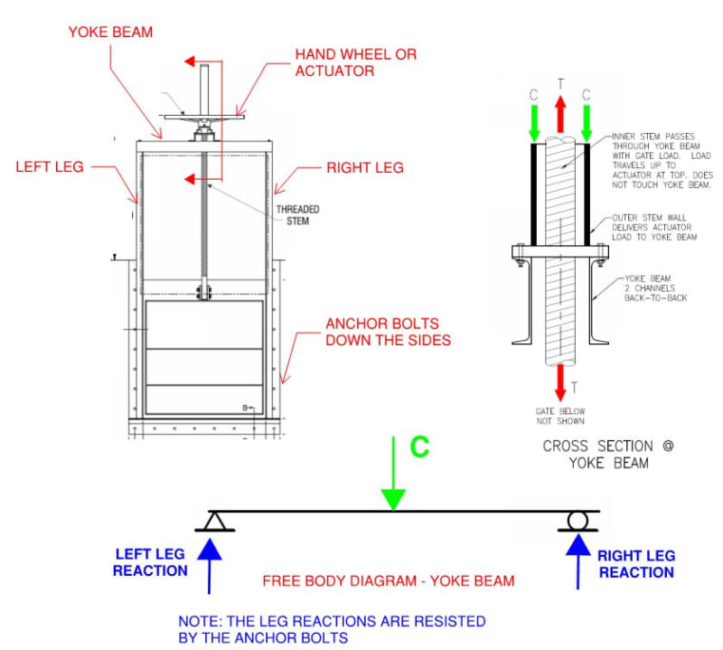
Self Contained Sluice Gate Actuator Stall Load Structural Engineering General Discussion Eng Tips
2
Model Of The Sluice Gate Download Scientific Diagram
0 komentar
Posting Komentar